System Sensor Hornstrobe Wiring Diagram
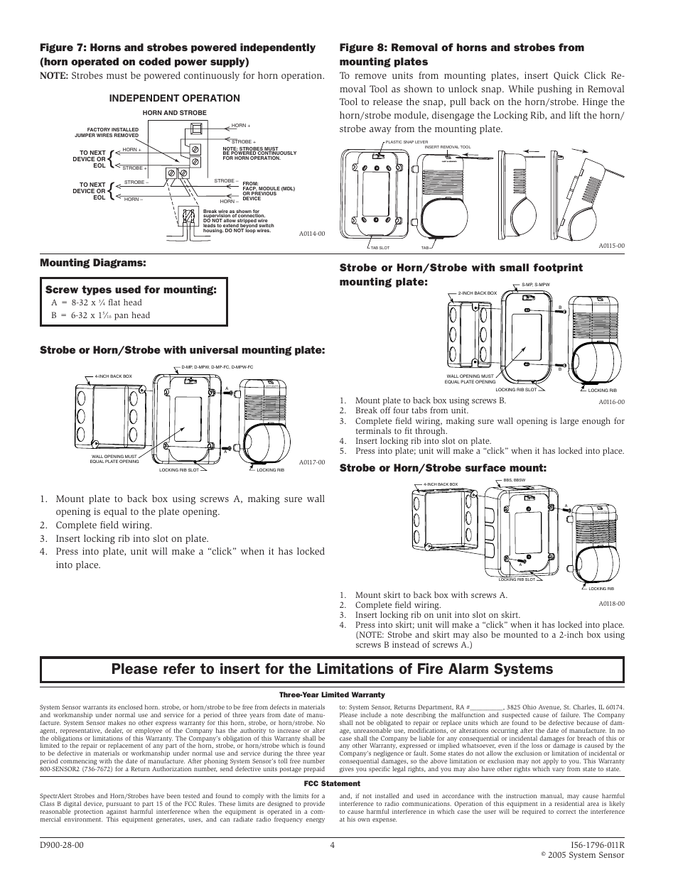
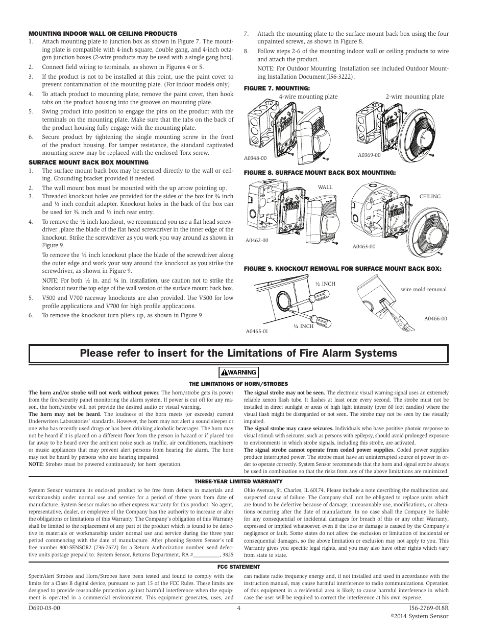
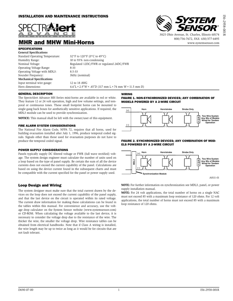
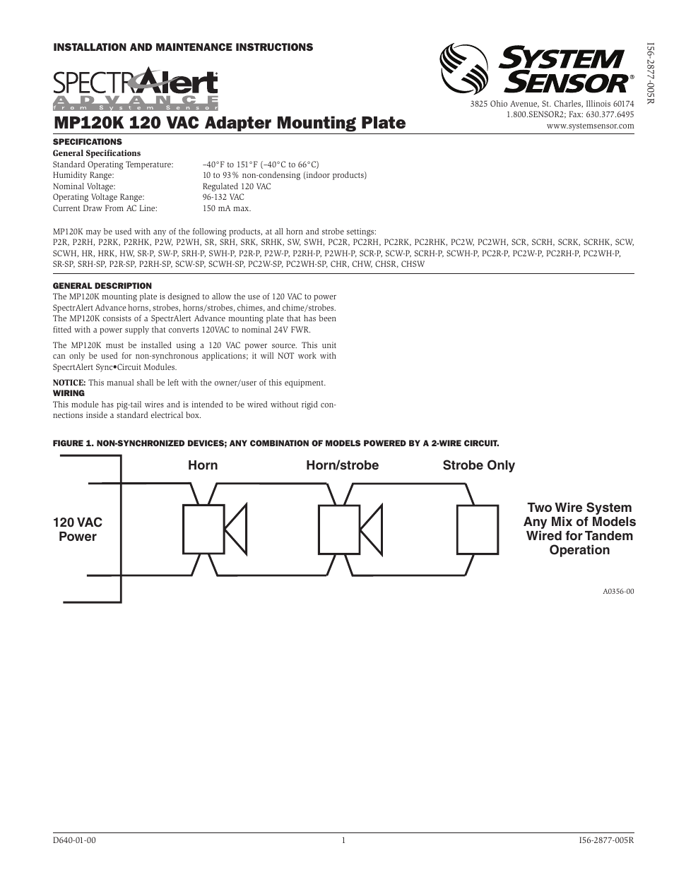
System sensor hornstrobe wiring diagram. With white and red plastic housings wall and ceiling mounting options System Sensor L-Series can meet virtually any application requirement. The System Sensor MDL3 module may be used to provide synchronization. Line in and out A0475-01 SYSTEM WIRING The 2-wire horn strobe chime strobe and strobe only require two wires for power and supervision.
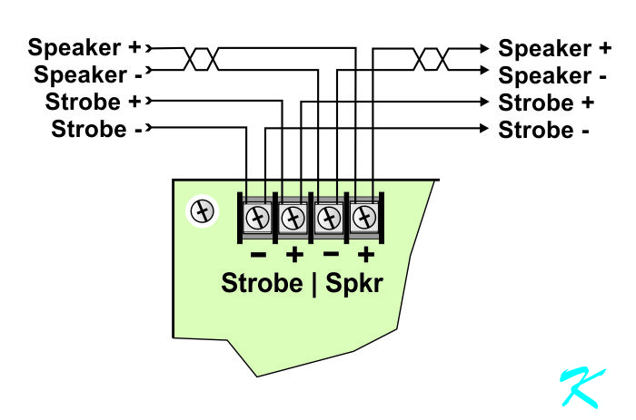
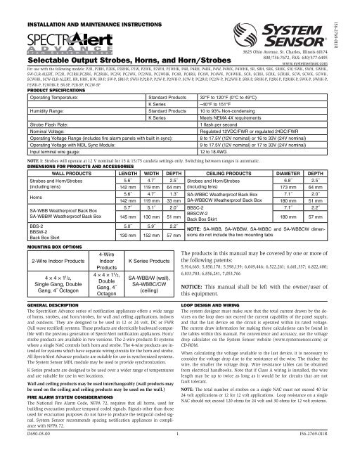
NFPA 72 guidelines should be observed. Product Documentation Drawings. The 4-wire products are in - tended for systems which have separate wiring circuits for the horn and strobe.
Each component should be set and linked to other parts in specific manner. 141g MASS Series HornStrobes. Line in and out 2.
293g Operating Temperature Range. A wiring diagram is a streamlined standard pictorial representation of an electric circuit. Vices can be activated by a compatible fire alarm control panel or power sup- ply.
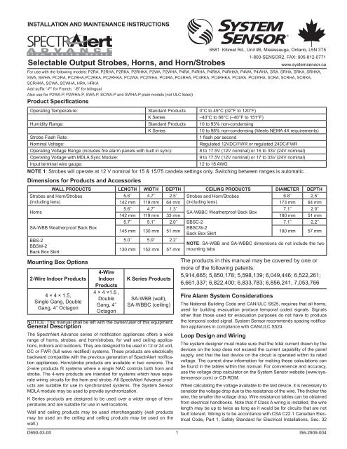
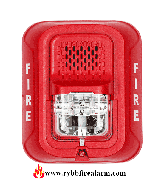
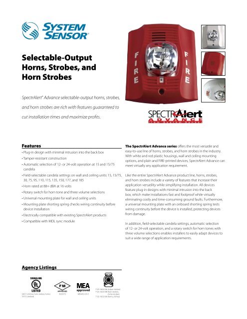
With white and red plastic housings standard and compact footprint devices System Sensor L-Series can meet virtually any application requirement. Line in and out 3. This manual should be left with the owneruser of this equipment.
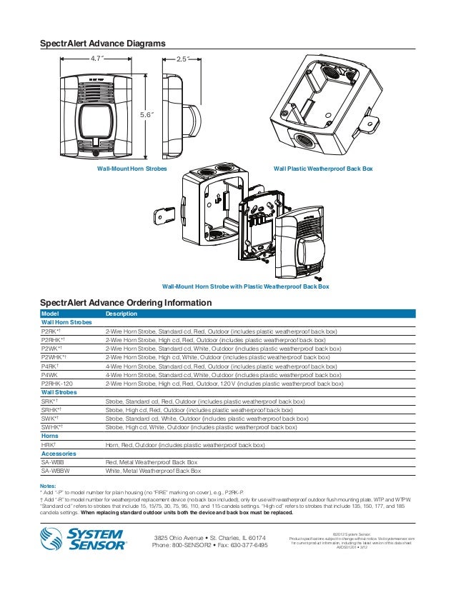
Standard Horn Strobe 56 143mm 47 119mm 125 32mm. Automatic selection of 12- or 24-volt operation at 15 and 1575 candela. The Genesis Temporal Horn-Strobe is a fire alarm notification The strobe includes a field-configurable switch for selecting the Figure 3.
System Sensor Horn Strobe Wiring Diagram Great Installation Of Fire Alarm Horn Strobe Wiring Diagram. Otherwise the arrangement will.
Vices can be activated by a compatible fire alarm control panel or power sup- ply.
All SpectrAlert Advance products are suitable for use in synchronized systems. Weatherproof per NEMA 4X IP56. Please read the System Smoke Detectors Application Guide which provides detailed information on detector spacing placement zoning wiring and spe - cial applications. The Genesis Temporal Horn-Strobe is a fire alarm notification The strobe includes a field-configurable switch for selecting the Figure 3. The first element is symbol that indicate electrical element from the circuit. Otherwise the arrangement will. It reveals the elements of the circuit as simplified shapes and the power and signal links in between the tools. The SpectrAlert Advance PC4RKA-R replacement model is a red four-wire ceiling-mount outdoor horn strobe with selectable strobe settings of 15 1575 30 75 95 110 and 115 cd. The horn strobe shall be wired as a primary-signaling notification appliance and comply with the Americans with Disabilities Act requirements for visible signaling appliances flashing at 1 Hz over the strobes entire operating voltage range.
Figure 4 wiring for coded supplies warning system sensor mdl3r and mdl3w user manual page 2 sa tr hs trc trw trcw manualzz home security s1224mc users apa151 installation maintenance instructions pdf manualslib horn strobe diagram 89 chevy 1500 pipiiing layout dvi d jeanjaures37 fr fire alarm 3 ford 2005 cts lsa nescafe cappu p2r zck 1 datasheet Read More. CAUTION Factory finish should not be altered. 18 12 AWG Shipping Weight. Standard Horn Strobe 56 143mm 47 119mm 125 32mm. Vices can be activated by a compatible fire alarm control panel or power sup- ply. The L-Series PC4RLA red or PC4WLA white is a four-wire ceiling-mount horn strobe with selectable strobe settings of 15 30 75 95 115 150 and 170 cd. The strobe light shall consist of a xenon flash tube and associated lensreflector system.





.png)


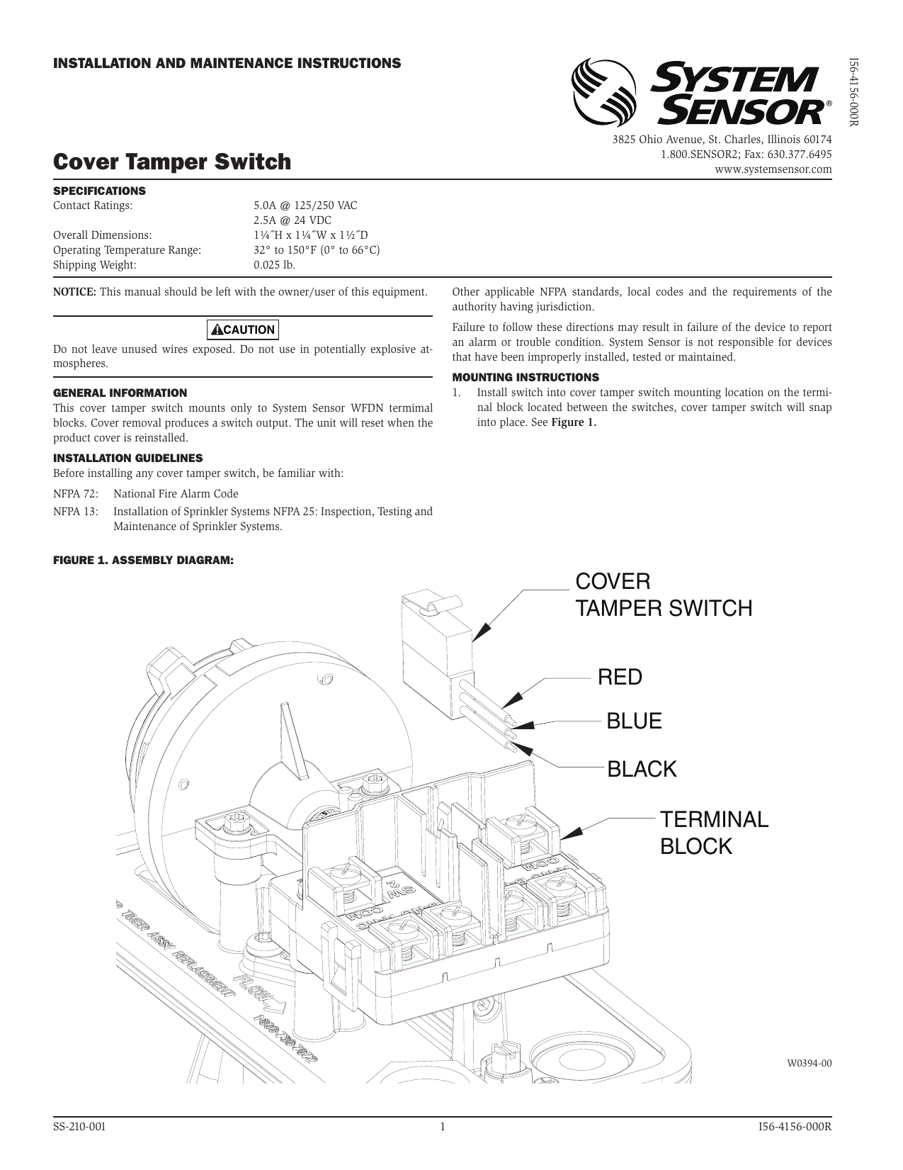

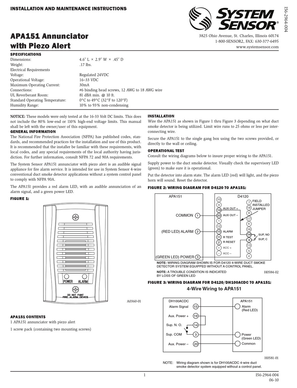

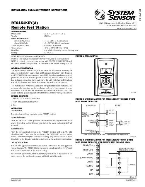











Post a Comment for "System Sensor Hornstrobe Wiring Diagram"